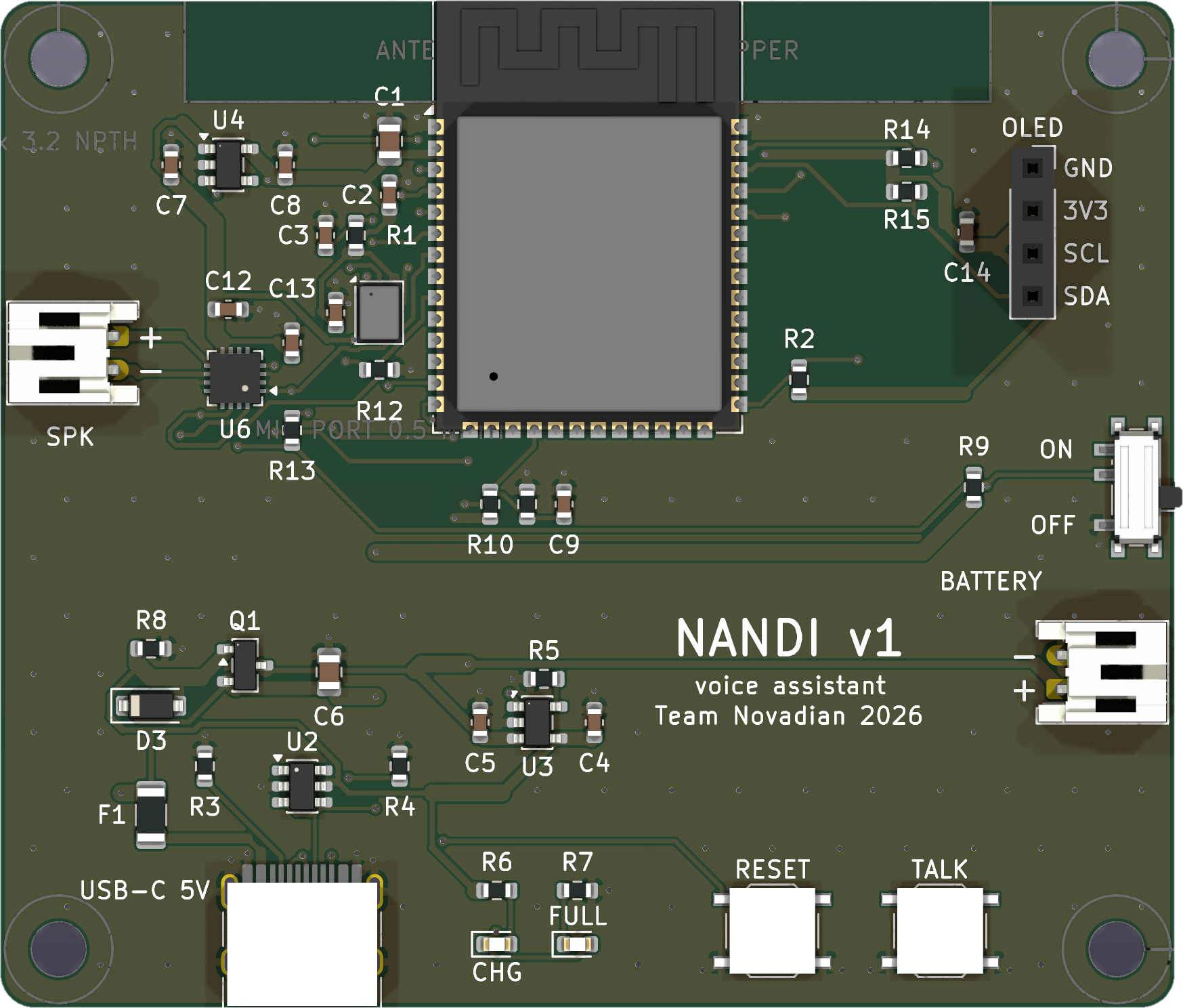
A breadboard full of wires is fine for a demo. It is not fine for a product that sits in a kitchen for years. So when we built Nandi, our voice assistant, we designed its main board ourselves. Here is how, step by step.
1. Start with what the device must do
Before any part numbers, we wrote down the jobs: listen to a voice, play a voice back, show a face on a small screen, run on a battery, and charge from USB-C. Every part on the board exists for one of those jobs.
2. Pick the brain
We chose a ready-made wireless module with Wi-Fi, Bluetooth and plenty of memory: sound and the wake-word model need room to work. It also talks USB directly, so the board needs one chip fewer.
A module, instead of a bare chip, brings a tested antenna and radio. The price: the antenna must sit at the board edge, with no copper under it or around it.
3. Sound in, sound out
- In: a digital microphone. It sends sound over a simple digital link, so there is no analog noise to fight. It hears through a tiny hole in the board, so the case needs an opening there too.
- Out: a small digital amplifier on the same kind of link, driving the speaker.
4. Power without surprises
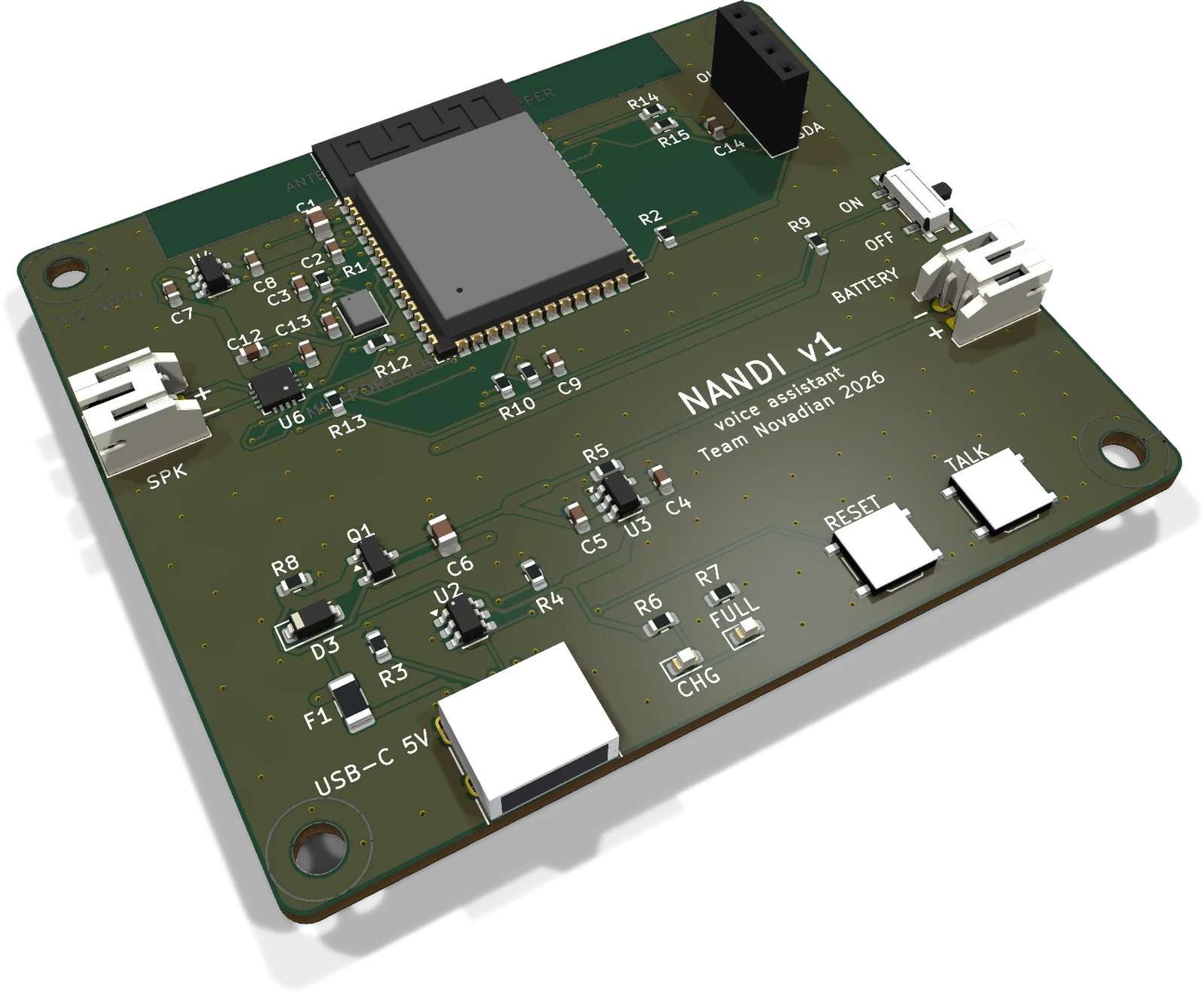
A small charger chip charges the battery from USB-C. Two parts switch between USB and battery by themselves, so the device never stops when you plug it in. One regulator makes a steady voltage for everything, a slide switch turns it all off, and the firmware can read how full the battery is.
5. Lay it out with care
The board is 70 × 60 mm with two copper layers. Each power pin gets its decoupling capacitor right next to it. Both layers are filled with ground, joined by many small vias. Power tracks are up to 1 mm wide, and the USB tracks are 0.2 mm.
6. Check everything before ordering
We ran the electrical rule check and the design rule check with the factory’s own rules. Both show zero errors and zero warnings, nothing is left unconnected, and the schematic and the board match exactly.
7. Describe the board in code
One file holds every part and every connection. Scripts turn it into the schematic, the layout, the routed board and finally every file the factory needs to make and assemble it. When something changes, we change one file and run the scripts again.
8. Be honest about the limits
The first layout was routed by an auto-router and then tidied by script. Every rule check passes, but rule checks cannot see everything. So the plan is simple: an electronics engineer reviews the layout, we order five boards first, and we check every part’s position in the factory’s preview before paying.
What we would tell you
Write down the jobs first. Pick a module, not a bare chip, for your first product. Check everything twice, and order a few boards before a batch. If you want help with any of these steps, that is what our hardware service is for.